

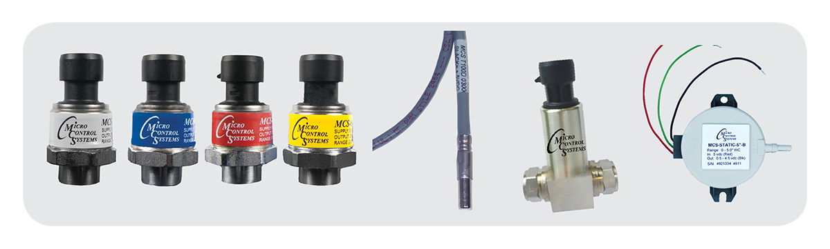
MCS carries a variety of Sensors including temperature sensors, humidity sensors, current sensors, pressure sensors, voltage sensors and CO2 sensors. All sensors are tested in house prior to being shipped.

| Part Number | Minimum Temperature range | Maximum Temperature range | Cable Length |
|---|---|---|---|
| MCS-T100-20 | −40°F −40°C |
+248°F +120°C |
20 Feet |
| MCS-T100-40 | −40°F −40°C |
+248°F +120°C |
40 Feet |
| MCS-T100-60 | −40°F −40°C |
+248°F +120°C |
60 Feet |
| MCS-T100-L-20 | −60°F −51°C |
+48°F +9°C |
20 Feet |
| MCS-T100-L-40 | −60°F −51°C |
+48°F +9°C |
40 Feet |
| Description |
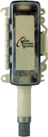
-40° to +248°F (-40° to +120°C) temperature sensor in a stainless
steel deep drawn tube with 20', 40', or 60' of 2 conductor
shielded cable. |
|---|---|
| Spec Sheets |
MCS-T100 Spec Sheet MCS-T100-L Spec Sheet |
| Installation | MCS-T100 Installation |
| Application Notes |
APP059A - SUCTION SIDE Installing a MCS-T100
Temperature Sensor |
| Part Number | Minimum Temperature range | Maximum Temperature range | Cable Length |
|---|---|---|---|
| MCS-T100-AVG-20 | 32°F 0°C |
+158°F +70°C |
20 Feet |
| Description |
32° to +158°F (0° to +70°C) temperature range for four MCS-T100-20 sensors that all connect to our five input board that communicates with the MCS-Magnum to average the four sensors. |
|---|---|
| Spec Sheets | MCS-T100-AVG-20 Spec Sheet |
| Installation | MCS-T100-AVG-20 Wiring Diagram |
| Part Number | Minimum Temperature range | Maximum Temperature range | Cable Length | Accessories |
|---|---|---|---|---|
| MCS-T300 | −22°F −30°C |
+125°F +51.6°C |
20 Feet | YES See Below |
| MCS-T300-L | −76°F −60°C |
+32°F +0°C |
20 Feet | YES See Below |
| MCS-T300-H | +32°F 0°C |
+250°F +121.1°C |
20 Feet | YES See Below |
| Description |
-22° to +125°F (-30° to +51.6°C) temperature sensor in nickel plated copper deep drawn tube with 20' of 3 conductor shielded cable. |
|---|---|
| Spec Sheets |
MCS-T300 Spec Sheet MCS-T300-L Spec Sheet MCS-T300-H Spec Sheet |
| Installation |
MCS-T300 Installation MCS-T300-L Installation |
| Application Notes |
APP046 - MCS-T300, MCS-T300HT, and MCS-T300LT Temperature Sensor Input to MCS-MAGNUM |
| Part Number | Diameter | Tube Length | Overall Length |
|---|---|---|---|
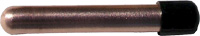
| MCS-TUBE | 0.425" OD 0.355" ID |
2.75" | 20.75" |
| Description |
Thin walled deep drawn copper tube 2¾" long with an 0.425" outside diameter filled with heat transfer grease. Designed to hold a MCS-T100 temperature sensor. |
|---|---|
| Spec Sheets |
MCS-TUBE+WELL Spec Sheet |
| Dimensional Drawings |
MCS-TUBE 3D
|
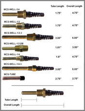
| Part Number | Diameter | Tube Length | Overall Length |
|---|---|---|---|
| MCS-WELL-1/4 | 0.400" OD 0.300" ID |
1.8" | 4.75" |
| MCS-WELL-1/4-3 | 0.400" OD 0.300" ID |
3.00" | 6.00" |
| MCS-WELL-1/2 | 0.400" OD 0.300" ID |
1.75" | 4.75" |
| MCS-WELL-1/2-3 | 0.400" OD 0.300" ID |
3.00" | 6.00" |
| MCS-WELL-1/2-DB | 0.400" OD 0.300" ID |
1.81" | 3.50" |
| MCS-WELL-3/4 | 0.400" OD 0.300" ID |
1.75" | 4.75" |
| Description |
A tube filled with heat transfer grease that has been soldered
onto a ¼", ½", or ¾" brass hex fitting with
NPT thread. Total length is 2½", 2¾", 3½",
3.68", or 4". |
|---|---|
| Spec Sheets |
MCS-TUBE+WELL Spec Sheet |
| Dimensional Drawings |
MCS-WELL 3D MCS-WELL-1/4 MCS-WELL-1/4-3 MCS-WELL-1/2 MCS-WELL-1/2-3 MCS-WELL-1/2-DB MCS-WELL-3/4 |
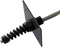
| Part Number | Minimum Inserting into Air Duct | Cable Length |
|---|---|---|
| MCS-SAIR-20 | 2.25" | 20 Feet |
| MCS-SAIR-40 | 2.25" | 40 Feet |
| MCS-SAIR-60 | 2.25" | 60 Feet |
| Description |
An MCS-T100 temperature sensor with an air supply bracket.
Mounting base is 2" x 2" and requires a minimum of 2.25" for
inserting into air duct. Comes with 20', 40', or 60' of 2
conductor shielded cable. |
|---|---|
| Spec Sheets |
MCS-SAIR Spec Sheet |
| Installation |
MCS-SAIR Wiring Diagram |
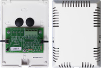
| Part Number | Description |
|---|---|
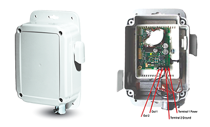
| MCS-ZONE-II | Temperature sensor board packaged in a plastic housing 4.30"w x 6.50"l x 2.25"h. |
| MCS-ZONE-II-OVR | MCS-ZONE-II with an override pushbutton |
| MCS-ZONE-II-OVR-T/R | MCS-ZONE-II with override pushbutton and target reset pushbutton |
| Spec Sheets |
MCS-ZONE-II Spec Sheet |
|---|---|
| Installation |
MCS-ZONE-II Wiring Diagram MCS-ZONE-II-OVR-T/R Wiring Diagram |
| Dimensional Drawings |
MCS-ZONE II 3D
|
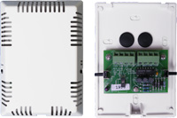
| Part Number | Description |
|---|---|
| MCS-HUMD-II | Combination humidity and ambient temperature sensor board packaged in a plastic housing 4.30"w x 6.50"l x 2.25"h. |
| MCS-HUMD-II-OVR | MCS-HUMD-II with override pushbutton |
| MCS-HUMD-II-OVR-T/R | MCS-HUMD-II with override pushbutton and target reset pushbutton |
| Spec Sheets |
MCS-HUMD-II Spec Sheet MCS-HUMD-II-OVR Spec Sheet MCS-HUMD-II-OVR-TR Spec Sheet |
|---|---|
| Dimensional Drawings |
MCS-HUMD II 3D
|
| Installation |
MCS-HUMD-II Wiring Diagram MCS-HUMD-II-OVR-T/R Wiring Diagram |
| Part Number | Description |
|---|---|
| MCS-HUMD-OS | Combination humidity and ambient temperature sensor board packaged in a plastic housing 2.82"w x 2.35"l x 7.98"h. |
| Part Number |
MCS-HUMD-OS |
|---|---|
| Description |
Combination humidity and ambient temperature sensor board
packaged in a plastic housing 4.30"w x 6.50"l x 2.25"h. |
| Spec Sheets |
MCS-HUMD-OS Spec Sheet |
| Dimensional Drawings |
MCS-HUMD-OS 3D
|
| Installation |
MCS-HUMD-OS Installation and Operation
Instructions |
| Part Number |
MCS-THERMOSTAT NOTE: Requires a configuration file for MCS-CONTROLLER from MCS Factory |
|---|---|
| Description |
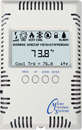
The MCS-THERMOSTAT is a temperature and humidity sensing smart
device with a backlit LCD display permitting remote adjustments
to the MicroMag controller. |
| Spec Sheets | MCS-THERMOSTAT Spec Sheet |
| Wiring Diagrams | MCS-THERMOSTAT Wiring Diagram |
| Dimensional Drawings |
MCS-THERMOSTAT 3D
|
| Documents | MCS-THERMOSTAT Installation & Reference
Manual |
| Part Number | Description |
|---|---|
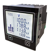
MCS-POWERMETER-B |
The MCS-POWERMETER-B is expertly designed for engineers who require a highly effective means of monitoring and displaying data. This panel-mounted 3-phase power meter is specifically tailored for mains circuits, potential transformers, and current transformers. With its multi-measurement capability for active and reactive power, it stands as the ideal choice for a diverse range of power monitoring applications, solidifying its position as the most flexible panel power meter for electrical monitoring. |
| Spec Sheets |
MCS-POWERMETER-B Spec Sheet MCS-POWERMETER-B-N Spec Sheet MCS-POWERMETER-B-MODBUS Spec Sheet |
|---|---|
| Installation |
MCS-POWERMETER Installation and
Startup |
| Part Number | Description |
|---|---|
| MCS-CT300 | 300:0.2 current transformer with circuitry to convert induced ac voltage into a 0-5vdc output voltage. Wire hole diameter: 1.00" |
| MCS-CT500 | 500:0.2 current transformer with circuitry to convert induced ac voltage into a 0-5vdc output voltage. Wire hole diameter: 2.05" |
| MCS-CT750 | 750:0.2 current transformer with circuitry to convert induced ac voltage into a 0-5vdc output voltage. Wire hole diameter: 2.05" |
| MCS-CT1500 | 1500:0.2 current transformer with circuitry to convert induced ac voltage into a 0-5vdc output voltage. Wire hole diameter: 4.25" |
| Spec Sheets |
MCS-CT300 Spec Sheet MCS-CT500 Spec Sheet MCS-CT750 Spec Sheet MCS-CT1500 Spec Sheet |
|---|---|
| Installation |
MCS-CT300 Wiring Diagram MCS-CT500 Wiring Diagram MCS-CT750 Wiring Diagram MCS-CT1500 Wiring Diagram |
| Dimensional Drawings |
MCS-CT300 3D
MCS-CT500 3D MCS-CT750 3D MCS-CT1500 3D |
| Part Number | Minimum PSI | Maximum PSI | Cable Length |
|---|---|---|---|
| MCS-150AC | 0 | 150 | Sensor Only |
| MCS-150AC-20M | 0 | 150 | 20 Feet |
| MCS-150AC-40M | 0 | 150 | 40 Feet |
| MCS-150AC-60M | 0 | 150 | 60 Feet |
| MCS-200C | 0 | 200 | Sensor Only |
| MCS-200C-20M | 0 | 200 | 20 Feet |
| MCS-200C-40M | 0 | 200 | 40 Feet |
| MCS-200C-60M | 0 | 200 | 60 Feet |
| MCS-500C | 0 | 500 | Sensor Only |
| MCS-500C-20M | 0 | 500 | 20 Feet |
| MCS-500C-40M | 0 | 500 | 40 Feet |
| MCS-500C-60M | 0 | 500 | 60 Feet |
| MCS-667C | 0 | 667 | Sensor Only |
| MCS-667C-20M | 0 | 667 | 20 Feet |
| MCS-667C-40M | 0 | 667 | 40 Feet |
| MCS-667C-60M | 0 | 667 | 60 Feet |
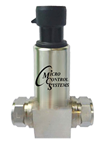
| Part Numbers |
MCS 150, 200, 500, & 667 PSI Pressure Transducers |
|---|---|
| Description |
Absolute psi gage pressure transducers with SAE female flare
fittings and Schrader valves. |
| Spec Sheets |
MCS-150AC Spec Sheet MCS-200C Spec Sheet MCS-500C Spec Sheet MCS-667C Spec Sheet |
| Dimensional Drawings |
MCS-PRESSURE TRANSDUCERS 3D MCS-150AC MCS-200C MCS-500C MCS-667C |
| Installation |
MCS Pressure Transducer Installation
Diagram |
| Documents |
AppNote MCS Transducer
Installation |
| Part Number | Description |
|---|---|
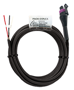
| PACK-CON-20 | Packard connector with 20' 3 wire shielded cable for MCS pressure transducers. |
| PACK-CON-40 | Packard connector with 40' 3 wire shielded cable for MCS pressure transducers. |
| PACK-CON-60 | Packard connector with 60' 3 wire shielded cable for MCS pressure transducers. |
| Spec Sheets |
PACK-CON |
| Dimensional Drawings |
PACK-CON 3D
|
| Installation |
PACK-CON Installation |
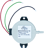
| Part Number | Minimum Inches WC | Maximum Inches WC |
|---|---|---|
| MCS-STATIC-0.2" | 0 | 0.2 |
| MCS-STATIC-5"-B | 0 | 5.0 |
| MCS-STATIC-50" | 0 | 50.0 |
| Spec Sheets |
MCS-STATIC-0.2" Spec Sheet MCS-STATIC-5" Spec Sheet MCS-STATIC-50" Spec Sheet |
|---|---|
| Dimensional Drawings |
PACK-CON 3D MCS-STATIC-0.2" MCS-STATIC-5" MCS-STATIC-50" |
| Installation |
MCS-STATIC-0.2 Wiring Diagram MCS-STATIC-5 Wiring Diagram |
| Part Number | Minimum Pressure Range | Maximum Pressure Range |
|---|---|---|
| MCS-050-DIFFB | 0 | 50 |
| Part Number |
MCS-050-DIFFB |
|---|---|
| Description |
Differential pressure transducer that is an economic and
durable option for dealing with differential-pressure
industrial applications. |
| Spec Sheets |
MCS-050-DIFFB Spec Sheet |
| Dimensional Drawings |
MCS-050-DIFFB 3D
|
| Application Notes |
MCS-050-DIFFB Wiring
Diagram |
| Part Number |
MCS-VOLTAGE-1PH |
|---|---|
| Description |
The MCS-VOLTAGE-1PH board accepts AC voltage inputs of
200vac to 600vac and generates a DC voltage output of
1.42vdc to 4.91vdc to a sensor input of an MCS-MAGNUM
micro controller that is programmed to convert this
signal to the corresponding AC voltage. |
| Spec Sheets |
MCS-VOLTAGE-1PH Spec
Sheet |
| Installation |
MCS-VOLTAGE-1PH Wiring
Diagram MCS-VOLTAGE Mounting Dimensions MCS-FUSE Mounting Dimensions |
| Dimensional Drawings |
MCS-VOLTAGE-3D
MCS-FUSE-3D |
| Part Number |
MCS-VOLTAGE-3PH |
|---|---|
| Description |
The MCS-VOLTAGE-3PH board accepts AC voltage inputs of
200vac to 600vac and generates three separate DC voltage
outputs of 1.42vdc to 4.91vdc to a sensor input of an
MCS-MAGNUM micro controller that is programmed to
convert this signal to the corresponding AC
voltage. |
| Spec Sheets |
MCS-VOLTAGE-3PH Spec
Sheet |
| Installation |
MCS-VOLTAGE-3PH Wiring
Diagram MCS-VOLTAGE Mounting Dimensions MCS-FUSE Mounting Dimensions |
| Dimensional Drawings |
MCS-VOLTAGE-3D
MCS-FUSE-3D |
| Part Number | Description |
|---|---|
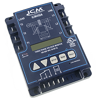
| MCS-PHASE | Three phase voltage monitor / 190-630vac 50-60Hz |
| Spec Sheets |
MCS-PHASE Spec Sheet |
|---|---|
| Installation |
MCS-PHASE Wiring Diagram |
| Dimensional Drawings |
MCS-PHASE-3D
|
| Part Number |
MCS-CONDUCTIVITY |
|---|---|
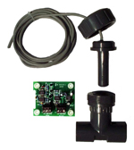
| Description |
The MCS-CONDUCTIVITY is a conductivity-to-voltage
transducer which takes its input from a carbon electrode
probe in a fluid stream and outputs a corresponding
voltage to a MCS micro controller. |
| Spec Sheets |
MCS-CONDUCTIVITY Spec
Sheet |
| Part Number | Description |
|---|---|
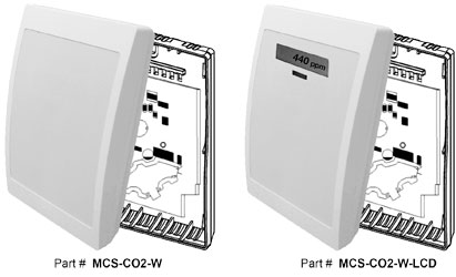
| MCS-CO2-W | The MCS-CO2-W measures the CO2 in a range of 0 to 2,000 ppm with an output of 0-5 VDC. |
| MCS-CO2-W-LCD | Carbon dioxide wall mount transmitter w/ LCD of CO2 level 4 Digits, 7 segments LCD with ppm indicator. |
| Spec Sheets |
MCS-CO2-W/MCS-CO2-W-LCD Spec
Sheet |
|---|---|
| Dimensional Drawings |
MCS-CO2-W-3D
|
| Installation |
MCS-CO2-W Mounting and Wiring
Instructions |
| Part Number |
MCS-CO2-D |
|---|---|
| Description |
The MCS-CO2-D measures the CO2 in a range of 0 to 2,000
ppm with an output of 0-5 VDC. |
| Spec Sheets |
MCS-CO2-D Spec Sheet |
| Dimensional Drawings |
MCS-CO2-D-3D
|
| Installation |
MCS-CO2-D Mounting and Wiring
Instructions |
| Part Number | Description |
|---|---|
| MCS-CO2-OA | The MCS-CO2-OA measures the CO2 in a range of 0 to 2,000 ppm with an output of 0-5 VDC. |
| Spec Sheets |
MCS-CO2-OA Spec Sheet |
|---|---|
| Installation |
MCS-CO2-OA Installation
Manual |